Activator supports OFTP V1 over X.25 as an alternative to OFTP V1 over TCP/IP. X.25 is an ITU-T standard protocol suite for packet-switched wide area network (WAN) communications. The following topics describe use of X.25 for outbound and inbound messages.
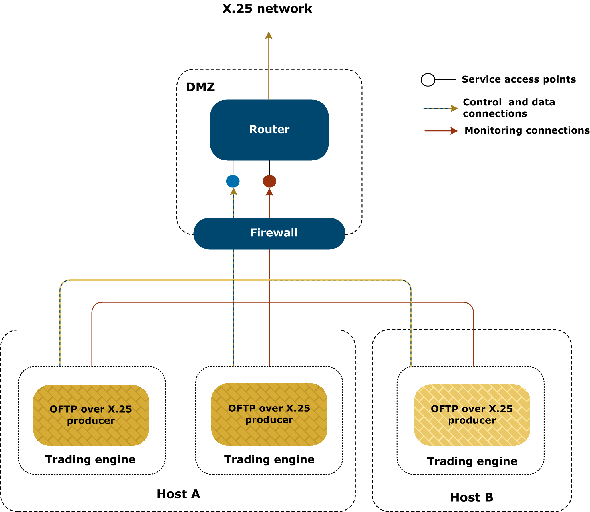
The following figure illustrates sending a message to a remote partner via X.25. The delivery is set up in a partner object.
Outbound calls are made when you contact a remote partner that hosts an OFTP over X.25 server. One router is associated to each partner delivery, but multiple deliveries can use the same router. For simplicity, the figure shows only one router; the setup is the same for multiple routers.
The following are the types of connections that are made when sending a message to a remote partner.
A control and data connection is established on the router on TCP port 146. This connection has two roles:
A monitoring connection is established on the SNMP UDP port defined in the router’s configuration. Activator uses this service to monitor the status of current connections. To make the connection, Activator has at least read access to the SNMP tables. This means a valid read-only community password must be entered in the router’s configuration in Activator user interface.
The following figure illustrates receiving a message from a remote partner via X.25. The delivery is set up in a community. The delivery uses an embedded OFTP server.
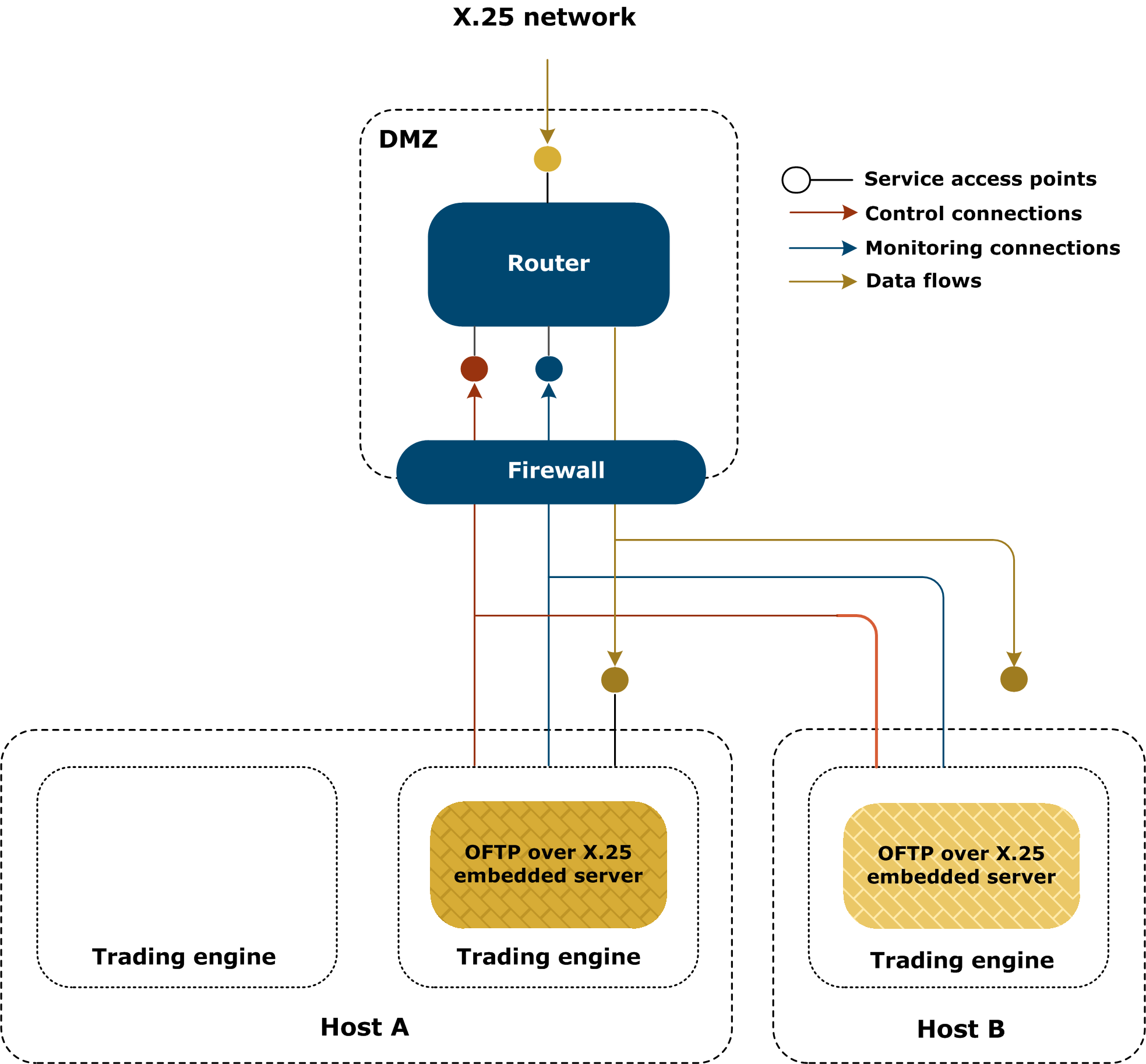
The previous figure shows a simple case with one embedded OFTP server per machine in a clustered configuration of Activator. Hosts A and B are two computers. Activator cluster has three processing nodes, two on host A and one on host B. As in a standard cluster, only one instance of an embedded server is started on each host.
The following figure illustrates a more complex case of multiple embedded OFTP over X.25 servers, using multiple routers. Two instances of Activator are shown on the same host for clarity, but in a cluster of multiple hosts the single distributed embedded server case applies to all embedded servers.
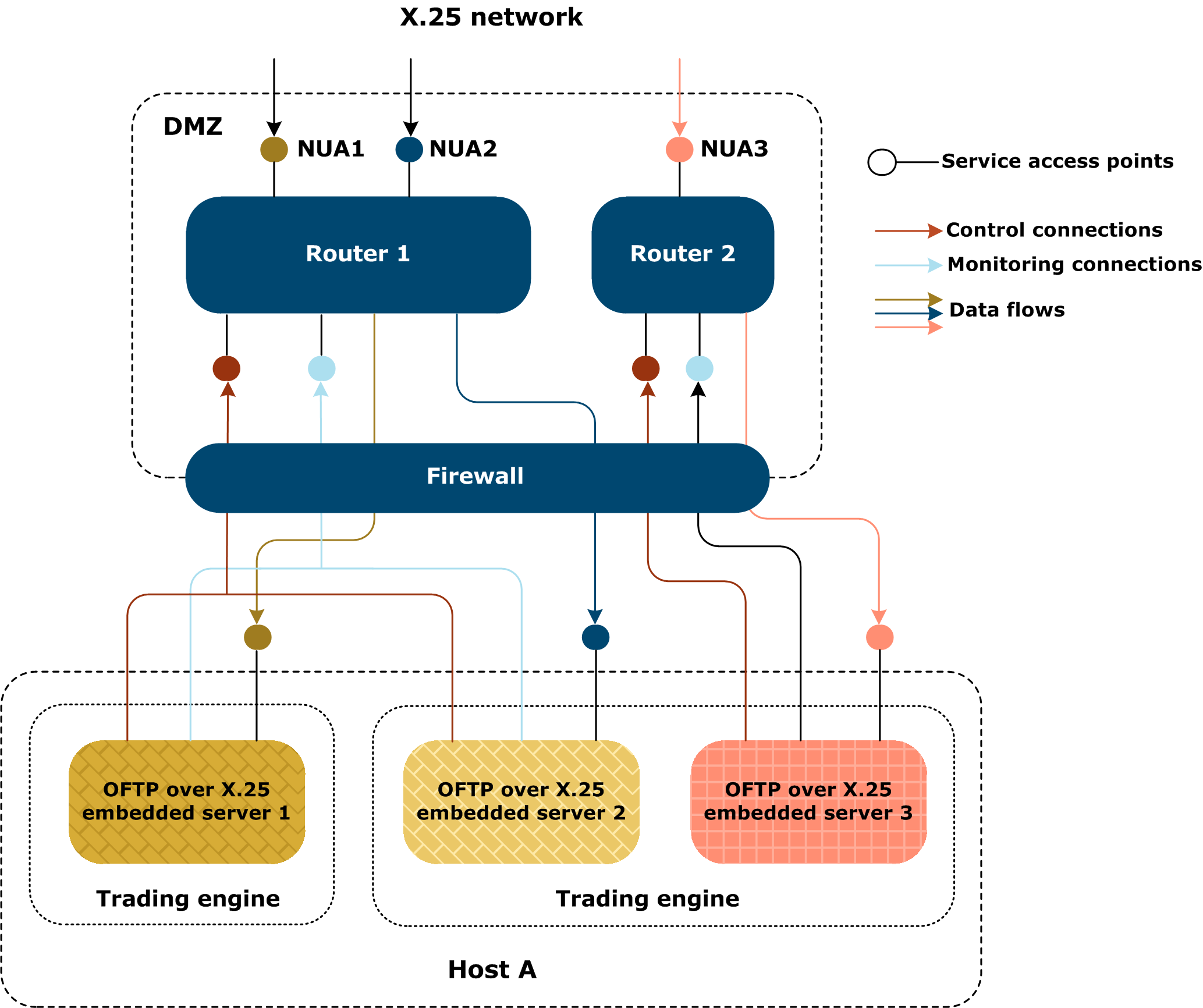
Points of importance in the multiple case are:
The following are the types of connections that are made when receiving a message from a remote partner.
A control connection is established on TCP port 146 on the router. Its role is to request the establishment of an X.25 access point on the router, linked to a call-back port opened on Activator. Once established, it controls the lifespan of this listening point. When the control connection is closed, so is the access point.
A monitoring connection has the same role as in outbound calls.
Inbound messages are received over the data connection. When Activator asks to establish an access point on the router, it also locally creates an access point. Each inbound X.25 call is transformed into its own separate TCP connection to this particular access point. Once the connection has been established, data are routed between TCP and X.25 the same way as with outbound calls.
NUA
Network user address identifies an X.25 endpoint. It can be local (corresponding to the identity of one of the routers) or remote (designating a partner’s endpoint).
SNMP
Simple Network Management Protocol is for monitoring and managing network hardware. Usually used over UDP on port 161 (port can be changed in the router’s configuration).
TP0 bridge
Service provided by the router, specified by RFC1086, to translate TP0-encapsulated packets from TCP to X.25 and back. The service is associated with TCP port 146 on the router (cannot be changed).